Posts By Eli Stewart
How is an Insert Coupling installed between two shafts, and what steps are involved in the installation process?
The installation of an Insert Coupling between two shafts involves a straightforward process.
Here are the steps typically involved in installing an Insert Coupling:
- Prepare the Shafts: Ensure that both shafts are clean and free of any contaminants. Remove any rust, burrs, or debris that might hinder a proper fit.
- Select the Appropriate Insert Coupling: Choose an Insert Coupling that matches the shaft diameters, torque requirements, and other specifications of your application.
- Place the Hubs on the Shafts: Slide the hubs of the Insert Coupling onto the shaft ends. The hubs have a central bore that fits over the shafts. Make sure the hubs are positioned at the desired location on each shaft.
- Align the Shaft Ends: Ensure that the shaft ends are properly aligned. Misalignment can be detrimental to the function and longevity of the Insert Coupling. The shafts should be as straight and parallel as possible.
- Install the Insert: The Insert Coupling typically consists of a flexible, elastomeric insert (e.g., spider or jaw) that goes between the hubs. Place the insert into the cavity between the hubs. The specific design of the insert may vary depending on the type of Insert Coupling.
- Secure the Hubs: Use the provided set screws or clamping mechanisms to secure the hubs to the shafts. Tighten these fasteners to the manufacturer’s recommended torque specifications. It’s important not to over-tighten, as this could damage the insert or cause premature wear.
- Verify Alignment: After the hubs are securely attached to the shafts, verify that the shafts remain aligned. Make any necessary adjustments to ensure proper alignment.
- Check for Proper Fit: Ensure that the insert is properly seated within the hubs and that there is no play or movement. If the insert is not seated correctly, disassemble and reposition it as needed.
- Lubrication (if necessary): Some Insert Couplings may require lubrication of the insert or the hubs. Consult the manufacturer’s recommendations for the type and amount of lubrication, if necessary.
- Final Inspection: After installation, perform a final visual inspection of the Insert Coupling and the entire system. Ensure that there are no loose fasteners, misalignment, or abnormalities.
- Operational Test: Run the machinery or system to verify that the Insert Coupling functions as expected. Pay attention to vibrations, noise, and any signs of misalignment. Address any issues that arise during testing.
- Regular Maintenance: As part of regular maintenance, periodically check the Insert Coupling for wear, misalignment, and proper tightness of set screws or clamping mechanisms. Replace the insert or perform any necessary maintenance tasks to maintain optimal performance.
Proper installation is essential to ensure the reliability and longevity of the Insert Coupling. It’s important to follow the manufacturer’s guidelines and recommendations for your specific Insert Coupling type, as different designs may have variations in installation procedures.
What are the key components and design features of an Insert Coupling that allow it to function effectively in mechanical systems?
The key components and design features of an Insert Coupling are critical to its effective functioning in mechanical systems. These features enable Insert Couplings to connect two shafts in a way that allows for torque transmission while accommodating slight misalignments and dampening shock and vibrations. Here are the key components and design features:
- Hubs: Insert Couplings consist of two hubs, one attached to each of the two shafts to be connected. The hubs are designed to provide a secure and rigid connection to the shafts. They typically have a bore that fits over the shafts.
- Insert: The insert is a flexible, elastomeric component that is placed between the two hubs. The insert’s design varies depending on the type of Insert Coupling (e.g., spider or jaw insert). The insert is the component responsible for transmitting torque and compensating for slight misalignments.
- Spider or Jaw: The insert is often referred to as a “spider” or “jaw.” These terms describe the shape and design of the insert. Spiders have multiple legs that provide flexibility and damping, while jaws have curved elements that grip the hubs securely. The choice of insert type depends on the specific application’s requirements.
- Lugs: Some Insert Couplings, particularly jaw-type couplings, may feature lugs on the hubs and the insert. The lugs are designed to interlock, creating a secure connection and transmitting torque efficiently.
- Fasteners: Insert Couplings may include set screws or clamping mechanisms that are used to secure the hubs onto the shafts. Insert Coupling These fasteners are tightened to ensure a firm attachment, preventing slippage during operation.
- Alignment Features: Insert Couplings often have alignment features or marks that assist in aligning the hubs and the shafts correctly. Proper alignment is crucial to the coupling’s performance and the longevity of the machinery.
- Material: Insert Couplings can be made from various materials, including steel, aluminum, and other alloys. The choice of material depends on factors such as the torque requirements, environmental conditions, and the specific application.
- Design for Shock Absorption: Many Insert Couplings are designed with features that allow them to absorb shock and dampen vibrations. This is particularly important in applications where machinery may be subjected to sudden loads or where smooth and stable operation is required.
- Misalignment Tolerance: Insert Couplings are designed to accommodate some degree of angular and parallel misalignment between the two shafts. The amount of misalignment tolerance varies depending on the specific coupling design and type of insert used.
- Easy Maintenance: Some Insert Couplings are designed for easy maintenance, allowing for quick disassembly and reassembly without the need for special tools or equipment.
- Configurations: Insert Couplings come in various configurations to meet specific application needs, including single-flex, double-flex, and spacer types. The choice of configuration depends on factors like the amount of misalignment and torque requirements.
These components and design features work together to create a reliable and effective connection between two shafts, allowing for the transmission of torque while compensating for misalignments and providing shock and vibration absorption. The specific design and materials of the Insert Coupling can vary based on the application’s demands.
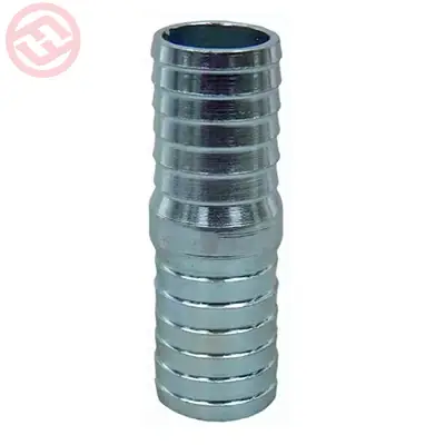
How does an Insert Adaptor create a reliable and leak-free connection between a PE pipe and another pipe material?
An Insert Adaptor creates a reliable and leak-free connection between a polyethylene (PE) pipe and another pipe material by using a combination of design features and a secure attachment method.
Here’s how it achieves a dependable connection:
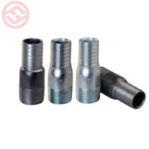
- Barbed or Ribbed Design: The Insert Adaptor typically has a barbed or ribbed design on one end. This design is essential for securely gripping the PE pipe. The barbs or ribs provide multiple points of contact, ensuring a tight and secure fit. The shape and spacing of these barbs or ribs are carefully engineered to maximize grip and prevent the PE pipe from slipping off.
- Watertight Seal: On the other end of the Insert Adaptor, there is a threaded or compression connection. This end is designed to connect to the other pipe material, which could be metal, PVC, or another material. The threaded or compression end incorporates sealing mechanisms, such as O-rings or gaskets, that create a watertight seal between the Insert Adaptor and the other pipe material. This seal prevents any leakage or seepage of fluids.
- Secure Attachment: The Insert Adaptor is typically installed by first sliding the PE pipe onto the barbed end. The barbs or ribs grip the PE pipe firmly, preventing it from slipping off during operation. Then, the threaded or compression end is securely attached to the other pipe material, completing the connection. The tight connection and sealing mechanism ensure that no fluid can escape the joint.
- No Welding Required: Unlike welding, which can be a complex and time-consuming process, Insert Adaptors eliminate the need for hot work. This not only simplifies the installation process but also reduces the potential for weld-related defects or errors that might lead to leaks.
- Ease of Installation: The installation of an Insert Adaptor is relatively straightforward and can often be carried out with standard plumbing tools. Insert Adaptor This ease of installation further contributes to the reliability of the connection, as it reduces the likelihood of errors during the installation process.
- Flexibility and Adaptability: Insert Adaptors can be used in various applications and projects where polyethylene pipes need to be connected to different pipe materials. Their flexibility and adaptability make them suitable for a wide range of plumbing and piping systems.
Overall, the combination of the barbed or ribbed design for secure attachment to the PE pipe and the sealing mechanism for the connection to the other pipe material ensures a reliable, leak-free connection when using an Insert Adaptor in a plumbing or piping system.
What factors should be considered when selecting the appropriate size and type of Insert Adaptor for a specific plumbing project?
Selecting the appropriate size and type of Insert Adaptor for a specific plumbing project is essential to ensure a reliable and leak-free connection. Several factors should be considered when making this choice:
- Pipe Size: The size of the polyethylene (PE) pipe and the pipe material you are connecting to with the Insert Adaptor are crucial. The Insert Adaptor should be compatible with the diameters of both pipes. Ensure that you choose an Insert Adaptor with the correct size to match the PE pipe as well as the other pipe material.
- Connection Type: Determine whether you need a threaded or compression-style Insert Adaptor. The choice often depends on the type of connection the other pipe material provides. Ensure that the Insert Adaptor’s connection type matches the requirements of your project.
- Material Compatibility: Consider the material of the Insert Adaptor. Common materials include brass, stainless steel, and high-density polyethylene (HDPE). Select an Insert Adaptor material that is compatible with the fluids or gases being transported and the other pipe material to prevent corrosion or material incompatibility issues.
- Pressure Rating: Ensure that the selected Insert Adaptor has an appropriate pressure rating for the specific application. The pressure rating should match or exceed the maximum pressure the system will experience.
- Temperature Range: Consider the temperature range of your plumbing system. Different materials have varying temperature tolerances. Ensure that the Insert Adaptor material can withstand the temperature conditions of your project without deformation or failure.
- Application Type: Consider the specific application for which the Insert Adaptor will be used. For example, in potable water systems, you may need to ensure that the materials are safe for drinking water. In industrial settings, the materials should be compatible with the transported substances.
- Environmental Conditions: Evaluate the environmental conditions of the installation location. If the plumbing system is exposed to harsh weather, chemicals, or corrosive substances, choose an Insert Adaptor that can withstand these conditions.
- Certifications and Standards: Verify that the Insert Adaptor complies with industry standards and regulations. Look for relevant certifications, such as those from NSF International for drinking water systems or industry-specific standards.
- Ease of Installation: Consider the ease of installation, especially if the project requires a quick or efficient setup. Some Insert Adaptors come with features that simplify the installation process.
- Cost: While cost is a factor, it should not be the sole determinant. Balance the cost of the Insert Adaptor with its suitability for the project, ensuring that you select a fitting that meets the necessary requirements.
- Supplier and Manufacturer: Choose a reputable supplier and manufacturer of Insert Adaptors. Reliable manufacturers often provide higher-quality products, and established suppliers can offer support and guidance in selecting the right components.
- Future Maintenance: Consider the ease of future maintenance or modifications to the plumbing system. If you anticipate changes or repairs in the future, a flexible and adaptable Insert Adaptor may be preferable.
By carefully considering these factors, you can select the most appropriate size and type of Insert Adaptor for your specific plumbing project, ensuring that it provides a secure and leak-free connection.
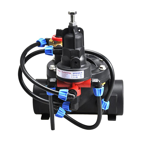
How do you install a pressure reducing valve in a plumbing system?
Installing a pressure reducing valve (PRV) in a plumbing system involves the following steps:
Gather Required Tools and Materials: Before starting the installation, gather the necessary tools and materials, including a pressure reducing valve, pipe wrenches, Teflon tape, pipe cutter, soldering equipment (if applicable), flux, and solder.
Locate the Installation Point: Identify the appropriate location for installing the PRV in the plumbing system. It is typically installed near the main water supply line, after the main shut-off valve.
Shut off the Water Supply: Turn off the main water supply to the building. This can usually be done at the water meter or the main shut-off valve.
Drain the Plumbing System: Open a faucet at the lowest point in the building to drain any remaining water from the plumbing system. This will help prevent water from flowing during the installation process.
Measure and Cut the Pipe: Measure the section of the pipe where the PRV will be installed. Use a pipe cutter to make a clean and straight cut at the designated location. Ensure that the cut is perpendicular to the pipe.
Prepare the Pipe Ends: Remove any burrs or sharp edges from the cut pipe ends using a deburring tool or a file. This will ensure a proper connection with the PRV.
Install the PRV: Apply Teflon tape to the male threads of the PRV to create a tight seal. Insert the PRV between the cut ends of the pipe and align it correctly. Use pipe wrenches to tighten the connections, ensuring a secure fit.
Connect the PRV to the Pipe: If the plumbing system uses copper pipes, solder the connections using a soldering torch, flux, and solder. Pressure Reducing Valve Follow proper soldering techniques and allow the joints to cool before proceeding.
Adjust the Pressure Setting: Some PRVs have an adjustable pressure setting. Refer to the manufacturer’s instructions to adjust the pressure to the desired level. Use a pressure gauge to monitor and verify the pressure adjustment.
Test the System: Turn on the main water supply and check for any leaks around the PRV. Also, check if the PRV is effectively reducing the incoming water pressure to the desired level. Adjustments may be necessary if the pressure is not within the desired range.
It’s important to note that the installation process may vary depending on the specific PRV model and the plumbing system configuration. Always refer to the manufacturer’s instructions and guidelines for detailed installation procedures and any specific considerations for your PRV model. If you are not comfortable with the installation process, it is advisable to seek the assistance of a qualified plumber.
What maintenance is required for pressure reducing valves?
Pressure reducing valves (PRVs) generally require minimal maintenance. However, regular inspections and occasional maintenance tasks can help ensure their optimal performance.
Here are some maintenance activities that may be required for PRVs:
Visual Inspection: Periodically inspect the PRV for any signs of leaks, corrosion, or physical damage. Look for water seepage around the valve body, connections, or fittings. If any issues are identified, take appropriate action, such as tightening loose connections or replacing damaged parts.
Pressure Adjustment: If your PRV has an adjustable pressure setting, you may need to periodically check and adjust the pressure as needed. Use a pressure gauge to measure the downstream pressure and compare it to the desired pressure range. Adjust the PRV if the pressure is outside the desired range.
Cleaning and Flushing: Over time, debris, sediment, or mineral deposits may accumulate in the PRV, affecting its performance. Cleaning the valve and associated pipes periodically can help maintain proper operation. Follow manufacturer guidelines to safely clean the PRV and associated plumbing components.
Testing and Functionality Check: Occasionally, test the PRV to ensure it is functioning correctly. Monitor the downstream pressure and verify that the PRV is reducing the incoming pressure to the desired level. If you notice any irregularities or inconsistent pressure, consider servicing or replacing the PRV.
System-wide Maintenance: In addition to PRV-specific maintenance, it is essential to maintain the overall plumbing system. Regularly inspect and maintain other components, such as water filters, pressure gauges, and shut-off valves. Address any issues promptly to prevent potential problems with the PRV.
Follow Manufacturer Guidelines: Always refer to the manufacturer’s maintenance instructions and guidelines specific to your PRV model. Manufacturers may provide additional maintenance recommendations or specify the recommended maintenance intervals for their products.
Remember that the maintenance requirements can vary depending on the specific PRV model, water quality, and system conditions. It is advisable to consult a professional plumber or follow the manufacturer’s recommendations for the most accurate and appropriate maintenance procedures for your PRV.
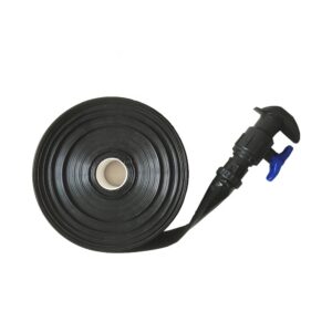
How do you install a micro spray tube in a garden or landscape?
Installing a micro spray tube in a garden or landscape involves the following steps:
Plan and Design: Determine the layout and irrigation needs of your garden or landscape. Identify the areas that require watering and the specific plants or zones that will be served by the micro spray tubes.
Select the Micro Spray Tube System: Choose a micro spray tube system that suits your watering requirements. Consider factors such as the flow rate, coverage area, and water distribution pattern of the micro spray heads.
Gather Materials: Collect all the necessary materials for installation, including the micro spray tubes, micro spray heads, connectors, stakes, and any additional fittings or accessories recommended by the manufacturer.
Prepare the Water Source: Ensure you have a suitable water source nearby, such as a garden hose or an irrigation system supply line. If needed, install a pressure regulator or filter to optimize the water pressure and quality for the micro spray tube system.
Lay Out the Micro Spray Tubes: Start by laying out the main micro spray tube along the desired watering areas. Cut the tube to the desired length using a tubing cutter or sharp knife. Lay the micro spray tubes in a straight line or follow the contours of the landscape.
Install Micro Spray Heads: Attach the micro spray heads to the micro spray tubes at the appropriate intervals, depending on the watering needs of the plants or zones. Make sure the spray heads are securely attached and facing the desired direction.
Connect the System: Use connectors or fittings to join the micro spray tubes, ensuring a watertight connection. If necessary, use tees or elbows to create branch lines for different watering zones or to navigate around obstacles.
Secure the Micro Spray Tubes: Use stakes or clips to secure the micro spray tubes to the ground. This helps prevent movement or displacement during operation and protects them from accidental damage.
Test the System: Turn on the water supply and check for any leaks or issues with water flow. Adjust the water pressure if needed using a pressure regulator. Ensure that the micro spray heads are providing the desired spray pattern and coverage.
Fine-tune and Maintain: Make any necessary adjustments to the micro spray heads’ positions or angles to achieve optimal coverage. Regularly inspect the system for leaks, clogs, or damaged components. Clean or replace clogged or malfunctioning micro spray heads as necessary.
Remember to consult the manufacturer’s instructions and guidelines specific to your micro spray tube system for detailed installation procedures and any additional considerations.
What are the key features and components of a micro spray tube?
The key features and components of a micro spray tube system typically include:
Micro Spray Tubes: These are flexible tubes made of durable materials such as polyethylene or PVC. They come in various lengths and diameters and are designed to deliver water to the micro spray heads.
Micro Spray Heads: Micro spray heads are the nozzles or emitters that release water in a fine spray pattern. They are attached to the micro spray tubes and come in different types, such as fixed spray heads, adjustable heads, or rotating heads, allowing for customization of the watering pattern and coverage area.
Connectors and Fittings: Connectors and fittings are used to join the micro spray tubes together or to connect them to the water source. micro spray tube These components ensure a secure and leak-free connection between the different parts of the micro spray tube system.
Stakes or Clips: Stakes or clips are used to secure the micro spray tubes to the ground, keeping them in place and preventing movement or displacement during operation. They help maintain the desired alignment and protect the system from accidental damage.
Pressure Regulators: Pressure regulators are optional components but can be included in the system to control and maintain the desired water pressure. They help ensure optimal operation of the micro spray heads and prevent over or under-watering.
Filters: Filters can be integrated into the micro spray tube system, especially if the water source contains debris or sediments. They help prevent clogging of the micro spray heads and maintain proper water flow and distribution.
Optional Accessories: Depending on the specific micro spray tube system, there may be additional optional accessories available, such as tubing cutters for precise tube length adjustments, tees or elbows for branching or direction changes, and plugs or end caps for sealing off the system.
These components work together to create a customizable and efficient micro spray tube system for precise and targeted irrigation in gardens, landscapes, or specific plant zones. It is important to consult the manufacturer’s instructions and guidelines for the specific micro spray tube system you are using to ensure proper installation and operation.
What is the material used for the fly knitting upper of these sneakers?
The material used for the fly knitting upper of the “Fly Knitting Sneakers Octopus Cuttlefish Shoe Unisex” would depend on the specific product or brand. Fly knitting typically refers to a type of knitting technique used to create a lightweight and flexible upper for sneakers. It involves using specialized machines to knit the upper in a single piece, resulting in a seamless and sock-like construction.
The specific material used in fly knitting can vary, but it often involves synthetic fibers such as polyester or nylon. These materials are chosen for their stretchability, breathability, and durability. They allow for a snug and comfortable fit while providing ventilation to keep the feet cool.
It’s worth noting that different brands may have their own proprietary versions of fly knitting, each with their own specific materials and technologies. Therefore, it’s always recommended to refer to the product description or consult the manufacturer for detailed information on the material composition of the specific “Fly Knitting Sneakers Octopus Cuttlefish Shoe Unisex” you are referring to.
What type of outsole or traction does the shoe have?
The specific type of outsole or traction pattern of the “Fly Knitting Sneakers Octopus Cuttlefish Shoe Unisex” would depend on the brand and model of the shoe. However, there are several common types of outsoles that are commonly used in sneakers. Here are a few possibilities:
Rubber Outsole: Many sneakers feature a rubber outsole, which provides good traction on various surfaces. Rubber outsoles are durable, flexible, and offer reliable grip.
Patterned Tread: The outsole may have a specific pattern or tread design to enhance traction. This can include patterns with grooves, lugs, or multidirectional treads that help to improve grip on different terrains.
Non-Slip Outsole: Some sneakers are designed with a non-slip or slip-resistant outsole. This type of outsole is particularly useful in environments where there may be wet or slippery surfaces, providing better stability and reducing the risk of slipping.
Multi-Surface Traction: Certain sneakers are designed to provide traction across various surfaces, such as indoor and outdoor environments. These outsoles may have a versatile tread pattern that performs well on both smooth and rough surfaces.
Specialized Traction: In some cases, sneakers designed for specific activities or sports may have specialized traction patterns. fly knitting sneakers octopus cuttlefish shoe unisex For example, running shoes may have a different outsole design compared to basketball shoes or hiking shoes, as each sport or activity may require specific traction characteristics.
It’s important to note that the specific type of outsole or traction pattern can vary among different models and brands. To get accurate information about the outsole and traction of the “Fly Knitting Sneakers Octopus Cuttlefish Shoe Unisex,” it’s best to refer to the product description or consult the manufacturer’s specifications for that particular shoe.

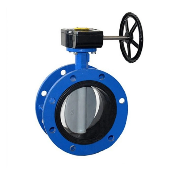
Can butterfly valves handle abrasive or corrosive fluids?
Butterfly valves can handle abrasive or corrosive fluids, but the extent of their suitability depends on several factors such as the valve design, materials of construction, and the specific characteristics of the fluid being handled.
Here are some considerations:
Valve Design: The design of the butterfly valve can impact its ability to handle abrasive or corrosive fluids. Valves with a resilient seat, such as those made with elastomers like EPDM or PTFE, provide better resistance to corrosion and can handle certain abrasive fluids. However, they may have limitations when it comes to highly abrasive or corrosive media.
Material Selection: The choice of materials for the valve body, disc, and seat plays a crucial role in determining its suitability for abrasive or corrosive fluids. Different materials offer varying levels of resistance to abrasion and corrosion. For abrasive fluids, valves with hard materials like stainless steel or high-performance alloys can provide better resistance. For corrosive fluids, selecting materials that are specifically resistant to the corrosive properties of the fluid is important, such as exotic alloys or lined valves with materials like PTFE or rubber.
Coatings and Linings: In cases where the fluid being handled is highly corrosive, butterfly valves can be coated or lined with materials that offer additional protection. For example, valves can be coated with epoxy or other corrosion-resistant coatings, or they can be lined with materials like rubber or PTFE to provide a barrier between the fluid and the valve components.
Fluid Compatibility: It is essential to evaluate the compatibility of the specific fluid with the valve materials. Some fluids may be abrasive or corrosive to a degree that exceeds the capabilities of standard butterfly valves. In such cases, specialized valves or alternative valve types may be required.
Maintenance and Monitoring: When handling abrasive or corrosive fluids, regular maintenance and monitoring are crucial. Periodic inspections, cleaning, and replacement of worn or damaged components are necessary to ensure the valve continues to function properly and maintain its integrity.
It is essential to consult with valve manufacturers, engineers, or industry experts to determine the most suitable valve design and materials for specific abrasive or corrosive fluid applications. They can provide guidance based on their expertise and knowledge of the specific fluid characteristics and operating conditions.
What are the maintenance requirements for butterfly valves?
The maintenance requirements for butterfly valves can vary depending on factors such as the valve design, materials of construction, operating conditions, and the specific application.
Here are some general maintenance considerations for butterfly valves:
Regular Inspections: Perform routine visual inspections of the valve to identify any signs of wear, damage, or leakage. Inspect the valve body, disc, stem, and seat for corrosion, erosion, cracks, or other abnormalities. Check the sealing surfaces for signs of leakage or deterioration.
Lubrication: Ensure that the valve’s moving parts, such as the stem and disc, are properly lubricated. Lubrication helps to reduce friction, extend the service life of the valve, and ensure smooth operation. Follow the manufacturer’s recommendations for the type and frequency of lubrication.
Cleaning: Keep the valve clean and free from debris or contaminants that could interfere with its operation. Regularly remove any buildup or sediment that may accumulate on the valve surfaces or within the pipeline.
Tightening and Adjustment: Check the valve’s fasteners, such as bolts, nuts, and screws, to ensure they are properly tightened. Loose fasteners can lead to leakage or affect the valve’s performance. Additionally, check and adjust any packing gland or stem seal to maintain proper sealing integrity.
Actuator Maintenance: If the butterfly valve is equipped with an actuator (e.g., electric, pneumatic, or hydraulic), ggg50 butterfly valve follow the manufacturer’s guidelines for maintenance and inspection of the actuator. This may include checking the actuator’s functionality, lubrication, and calibration.
Replacement of Wear Parts: Over time, certain components of the butterfly valve may experience wear and require replacement. This can include the valve seats, seals, or other parts that may deteriorate due to the specific application or operating conditions. Regularly assess the condition of these components and replace them as needed.
Monitoring and Testing: Consider implementing a monitoring and testing program to evaluate the performance and integrity of the valve. This can involve periodic testing for leakage, flow capacity, or operation under different pressures and temperatures.
Documentation and Record-Keeping: Maintain records of maintenance activities, inspections, repairs, and any relevant data associated with the valve. This documentation can help track the valve’s history, identify trends, and facilitate future maintenance and troubleshooting.
It is important to note that specific maintenance requirements may vary based on the manufacturer’s recommendations, industry standards, and the unique characteristics of the valve and its application. Consult the valve manufacturer’s documentation or seek guidance from qualified professionals to ensure proper maintenance practices for your specific butterfly valve.
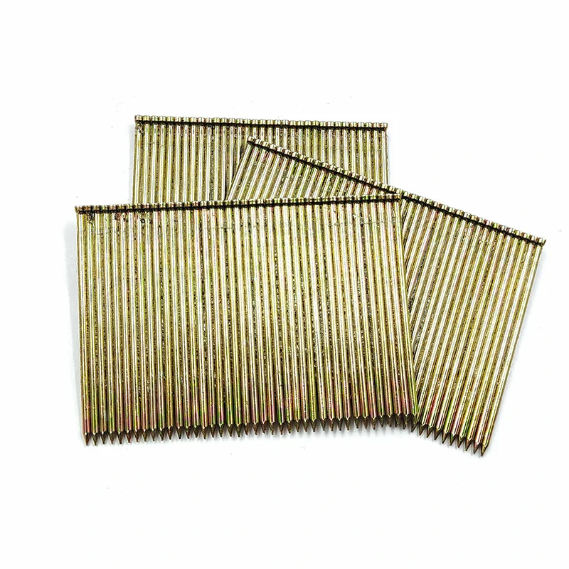
Reliable – Exploring the Applications of 1.5 Inch or 32mm Brad Nails and Stainless Brads
When it comes to woodworking, carpentry, and various crafting projects, the right fasteners are essential for secure and precise connections. In this comprehensive blog post, we will delve into the world of brad nails and explore the versatility and benefits of three key variants: 1.5 inch brad nails, 32mm nails for nail guns, and stainless brads. Join us as we uncover the applications and advantages of these reliable fasteners, providing you with the knowledge to select the perfect brad nail for your project needs.
1.5-Inch Brad Nails: Precision and Versatility
1.5-inch brad nails are a popular choice for a wide range of woodworking and carpentry applications. These nails are known for their slender profile and small heads, which allow for discreet and nearly invisible fastening. The 1.5-inch length strikes a balance between strength and flexibility, making them suitable for various projects.
One of the key advantages of 1.5-inch brad nails is their versatility. They can be used for delicate trim work, installing moldings, attaching thin panels, and other applications where a secure but inconspicuous fastening is required. Their small size also minimizes the risk of splitting or damaging the workpiece.
32mm Nails for Nail Guns: Efficiency and Convenience
32mm nails, specifically designed for nail guns, offer unparalleled efficiency and convenience in woodworking and construction projects. Nail guns, powered by compressed air or electricity, enable rapid and precise fastening, significantly reducing the time and effort required for manual hammering.
The 32mm length of these nails is ideal for a variety of applications, including framing, paneling, and general carpentry. Whether you’re constructing a wooden structure, assembling furniture, or installing cabinets, the use of 32mm nails in a nail gun ensures consistent and secure connections.
Stainless Brads: Durability and Corrosion Resistance
When working on projects that require resistance to corrosion or exposure to moisture, stainless brads are the optimal choice. These brads are made from stainless steel, a material known for its durability and ability to withstand rust and oxidation.
Stainless brads are essential for outdoor applications, such as deck construction, fencing, and boat building. They are also suitable for indoor projects in areas prone to humidity, such as bathrooms and kitchens. The corrosion resistance of stainless brads ensures that the fasteners remain intact and maintain their strength over time, contributing to the longevity of the project.
The Advantages of Brad Nails, 32mm Nails, and Stainless Brads
- Precision and Discreet Fastening: Brad nails, including 1.5-inch brad nails, allow for precise and inconspicuous fastening, ensuring a clean and professional finish.
- Efficient and Time-Saving: Nail guns equipped with 32mm nails enable rapid and efficient fastening, increasing productivity and reducing manual effort.
- Versatility: Brad nails and 32mm nails have a wide range of applications, making them suitable for various woodworking, carpentry, and construction projects.
- Durability and Corrosion Resistance: Stainless brads are highly durable and resistant to rust, making them ideal for outdoor and high-moisture environments.
- Reliable Connections: All three types of brad nails offer strong and secure connections, ensuring the longevity and structural integrity of the project.
Conclusion
Brad nails, including 1.5-inch brad nails, 32mm nails for nail guns, 18 ga brad nail 1 inch and stainless brads, are indispensable fasteners in woodworking, carpentry, and construction projects. The precision, efficiency, versatility, and durability they offer make them essential tools for professionals and DIY enthusiasts alike. By understanding the applications and advantages of these brad nails, you can confidently select the appropriate fastener for your specific project needs. Embrace the versatility and reliability of brad nails, 32mm nails, and stainless brads, and elevate the quality and efficiency of your woodworking endeavors.
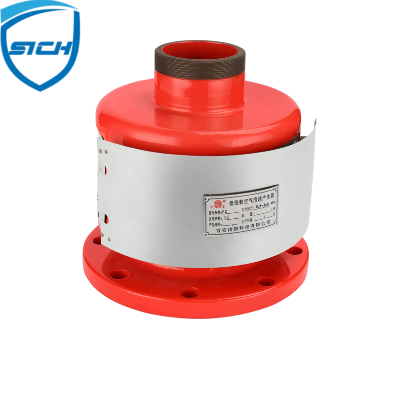
How is the installation of a low expansion foam chamber typically carried out?
The installation of a low expansion foam chamber is typically carried out following specific guidelines and procedures to ensure its proper functionality within a fire protection system.
Here’s an overview of the typical installation process:
System Design: Before installation, the fire protection system, including the low expansion foam chamber, is designed based on the specific requirements of the protected area. Factors such as the size of the area, fire hazards, and foam application rates are considered during the design phase.
Location and Placement: The location and placement of the low expansion foam chamber are determined based on the system design and the desired coverage area. The chamber is usually installed in a suitable location, such as above the hazard area or near the potential fire sources.
Mounting: The low expansion foam chamber is securely mounted to the structure or support using appropriate hardware. It should be installed in a stable position to ensure proper operation during a fire event.
Piping and Connections: The foam chamber is connected to the fire protection system piping. This includes the supply line for foam concentrate and water, as well as the necessary valves, fittings, and piping components. The piping system is carefully designed and installed to ensure proper flow and distribution of foam solution.
Foam Concentrate Supply: The low expansion foam chamber requires a supply of foam concentrate, which is mixed with water to generate foam. The foam concentrate supply system, including storage tanks, proportioning equipment, and appropriate piping, is installed and connected to the foam chamber.
Testing and Commissioning: Once the installation is complete, the low expansion foam chamber and the entire fire protection system undergo thorough testing and commissioning. This includes functional tests, flow tests, and verification of system performance to ensure that all components are working correctly and meeting the required specifications.
Documentation and Record-Keeping: Proper documentation of the installation process, including drawings, test reports, and equipment manuals, is essential. This documentation helps with future maintenance, inspections, and modifications, and ensures compliance with relevant regulations and standards.
It’s important to note that the installation process may vary depending on the specific manufacturer’s recommendations, china low expansion foam chamber local fire codes, and industry standards. Therefore, it is crucial to consult the manufacturer’s installation instructions and adhere to any applicable regulations and guidelines. Additionally, it is recommended to involve qualified fire protection professionals or contractors experienced in installing low expansion foam systems to ensure a safe and effective installation.
How does a low expansion foam chamber function in a fire protection system?
A low expansion foam chamber plays a vital role in a fire protection system by generating and distributing low expansion foam, which is used to suppress and extinguish fires.
Here’s how a low expansion foam chamber typically functions within a fire protection system:
Activation: When a fire occurs, the fire detection system, such as heat or smoke detectors, triggers the activation of the fire protection system, including the low expansion foam chamber.
Foam Solution Flow: Upon activation, a mixture of water and foam concentrate, known as foam solution, flows into the low expansion foam chamber. The foam solution is typically supplied from a foam concentrate storage tank through a proportioning system.
Mixing: Inside the low expansion foam chamber, the foam solution is mixed with air to generate low expansion foam. The chamber is designed with specific internal components, such as foam makers or foam generators, which create the required foam consistency.
Expansion: The foam generated in the low expansion foam chamber has a low expansion ratio, meaning it expands relatively less compared to other types of foam. This low expansion foam has a higher density and viscosity, making it suitable for certain fire hazards and applications.
Distribution: Once the low expansion foam is formed, it is discharged from the foam chamber into the protected area. The foam is distributed over the hazard area through piping, discharge devices (such as foam nozzles or sprinklers), or other distribution systems.
Fire Suppression: The low expansion foam blankets the fire, forming a layer that separates the fuel source from the surrounding air. This layer suppresses the fire by smothering the flames, cooling the fuel, and preventing the release of flammable vapors.
Post-Fire Protection: After the fire is extinguished, the low expansion foam provides post-fire protection by creating a foam blanket that helps to prevent re-ignition and provides a barrier against heat and potential re-flash.
The specific design and operation of a low expansion foam chamber may vary depending on the manufacturer, system requirements, and fire hazards being protected. It is essential to follow the manufacturer’s instructions and guidelines, as well as adhere to relevant fire codes and standards, to ensure the effective operation of the low expansion foam chamber in a fire protection system.
What are some tips for selecting the right size and fit of a diaper?
Selecting the right size and fit of a diaper is important to ensure comfort, leakage prevention, and overall effectiveness.
Here are some tips to consider when choosing the appropriate size and fit for a diaper:
Weight and Age Guidelines: Pay attention to the weight and age recommendations provided by the diaper manufacturer. These guidelines can serve as a starting point for selecting the right size.
Waist Size: Measure the waist circumference of the baby or refer to their clothing size to determine the appropriate diaper size. The diaper should fit snugly around the waist without being too tight or too loose.
Leg Openings: Check the fit around the baby’s legs. The diaper should have gentle elasticized leg cuffs that fit comfortably around the thighs, creating a barrier against leaks without leaving marks or causing discomfort.
Absorbency Capacity: Consider the baby’s needs in terms of absorbency. If the baby tends to have heavy wettings, selecting a diaper with a higher absorbency level or overnight specific diapers can help prevent leaks and keep the baby dry for a longer period.
Diaper Rise: The rise refers to the distance between the waistband and the crotch area of the diaper. Ensure that the rise is appropriate for your baby’s body shape. A proper rise helps prevent leakage from the front or back of the diaper.
Snug, but Not Too Tight: The diaper should fit snugly against the baby’s body, but it should not be overly tight. Tight diapers can cause discomfort, leave marks on the baby’s skin, and potentially restrict movement.
Check for Proper Coverage: Ensure that the diaper provides adequate coverage for the baby’s bottom. The back of the diaper should reach up to the waistline, and the front should cover the belly area without causing discomfort or excessive pressure on the baby’s tummy.
Consider Baby’s Mobility: If your baby is more active and mobile, look for diapers with stretchable side panels or a more flexible design. This allows for ease of movement and a better fit during various activities.
Monitor Leakage: If you notice frequent leaks or blowouts, it may indicate that the current diaper size is too small and it’s time to move up to the next size.
Trial and Error: Every baby is unique, and finding the right diaper size and fit may require some trial and error. Be open to trying different brands or sizes until you find the one that provides the best fit and comfort for your baby.
Remember, choosing the right size and fit is essential for the baby’s comfort and to prevent leaks. Regularly assess the fit as your baby grows and adjust the diaper size accordingly.
What are the key components of a disposable diaper?
A disposable diaper is composed of several key components that work together to provide comfort, absorbency, and leakage protection.
Here are the main components of a typical disposable diaper:
Outer Layer/Backsheet: The outer layer, also known as the backsheet, is the waterproof exterior of the diaper. It prevents moisture from leaking out of the diaper and keeps the baby’s clothing dry.
Inner Layer/Top Sheet: The inner layer, or top sheet, is the part of the diaper that comes into contact with the baby’s skin. It is typically made of a soft, diaper manufacturer non-woven material that wicks moisture away from the baby’s skin, keeping it dry and comfortable.
Absorbent Core: The absorbent core is the central part of the diaper responsible for absorbing and retaining liquid. It is usually made of a combination of superabsorbent polymers (SAP), wood pulp, and other absorbent materials. The core quickly absorbs urine and distributes it evenly throughout the diaper.
Elasticized Leg Cuffs: Elasticized leg cuffs are found around the leg openings of the diaper. They provide a snug fit and help prevent leaks by creating a barrier against leakage around the baby’s thighs.
Fastening System: The fastening system allows the diaper to be secured around the baby’s waist. It typically consists of adhesive tabs or hook-and-loop closures that can be adjusted and refastened as needed.
Waistband: The waistband of the diaper provides a comfortable and secure fit around the baby’s waist. It may have elastic properties to ensure a snug fit and prevent leakage.
Wetness Indicator: Some diapers feature a wetness indicator, typically a color-changing strip, that alerts caregivers when the diaper is wet and needs to be changed.
Breathability Features: Many disposable diapers incorporate breathability features such as micro-perforations or air channels that help promote airflow and reduce the risk of diaper rash.
Leakage Barriers: Leakage barriers, also known as standing leg gathers or leak guards, are additional barriers along the edges of the diaper that help contain liquid and prevent leaks, especially during active movements.
Adhesive Landing Zone: The adhesive landing zone refers to the area on the front of the diaper where the fastening tabs can be attached to secure the diaper in place.
These components work together to provide a comfortable and effective diapering experience, keeping the baby dry, protected, and minimizing the risk of leaks or skin irritation.
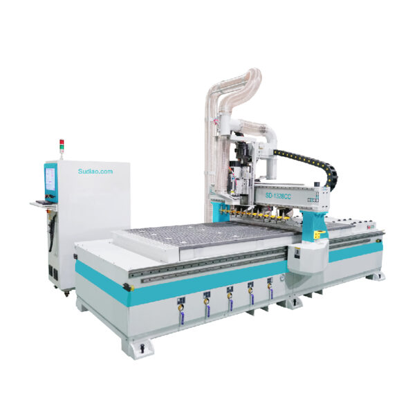
How does the CNC control system determine which tool to select for a specific machining operation?
The CNC control system determines which tool to select for a specific machining operation based on the instructions provided by the operator or programmed into the system.
Here’s an overview of how the CNC control system determines the tool selection:
Programmed Tool Information: The CNC control system relies on a program that contains the instructions for the machining operation. Within the program, the tools and their corresponding tool numbers or identifiers are specified.
Tool Table: The CNC control system maintains a tool table or tool library that associates tool numbers or identifiers with specific tools. The tool table includes information such as tool diameter, length, type, and other relevant parameters.
Tool Call-Up: When the CNC program reaches a point where a tool change is required, the control system refers to the tool number specified in the program. It looks up the tool table to retrieve the corresponding tool information.
Tool Availability: The control system checks the tool magazine or tool storage to ensure that the required tool is available. If the tool is not present in the magazine, an error or prompt may be displayed, indicating that the tool needs to be loaded.
Tool Change Sequence: If the required tool is available, the control system initiates the tool change sequence. It moves the machine to a designated tool change position away from the work area, ensuring safety during the tool change process.
Tool Selection and Installation: The control system commands the automatic tool changer (ATC) to select the designated tool from the tool magazine. automatic change tools cnc router manufacturer The ATC positions the new tool in the spindle and securely clamps it in place.
Tool Length Compensation: Some CNC systems incorporate tool length compensation features. The control system may automatically adjust the Z-axis position based on the tool’s length, ensuring accurate machining based on the tool’s geometry.
Machining Resumption: Once the tool change is complete, the control system moves the machine back to the work area, taking into account any tool length offsets if applicable. It resumes the machining process using the newly installed tool.
It’s important to note that the specific steps and terminology may vary depending on the CNC control system and the machine manufacturer. However, the general process involves referencing the programmed tool information, checking the tool table, and coordinating with the ATC to select and install the appropriate tool for the machining operation.
How does the CNC control system determine the tool length offsets for accurate machining?
The CNC control system determines tool length offsets to achieve accurate machining by using various methods and techniques. The specific method employed can depend on the capabilities of the CNC system and the machining requirements.
Here are a few common approaches:
Manual Entry: In some cases, the tool length offsets are manually entered into the CNC control system by the operator or programmer. This involves measuring the length of each tool and inputting the values into the control system’s tool table. The operator must ensure that the measurements are precise and updated whenever tool changes or adjustments are made.
Tool Length Measurement: Some CNC systems incorporate automatic or semi-automatic tool length measurement features. This may involve using a tool length measuring device, such as a tool presetter or a touch probe, to measure the length of the tool accurately. The measured values are then automatically entered into the control system’s tool table.
Probing and Tool Length Compensation: CNC systems equipped with probing capabilities can use touch probes to measure the actual length of the tool while it is installed in the spindle. The control system compares the measured length with the expected length stored in the tool table and calculates any necessary tool length offsets. These offsets are applied during machining to compensate for tool length variations, ensuring accurate positioning and machining results.
Laser Tool Measurement: Advanced CNC systems may employ laser tool measurement devices that can precisely measure tool lengths and diameters. Laser measurement systems can provide highly accurate and automated tool length offset data to the control system.
Once the tool length offsets are determined, the CNC control system applies these offsets during machining to compensate for any variations in tool length. The control system adjusts the Z-axis position based on the calculated tool length offsets, ensuring that the programmed tool paths accurately reflect the actual position of the cutting tool.
It’s important to note that the availability and implementation of tool length offset methods can vary among different CNC systems and machine manufacturers. The specific procedures and functionalities for determining tool length offsets can be found in the CNC system’s documentation or programming manuals provided by the machine manufacturer.